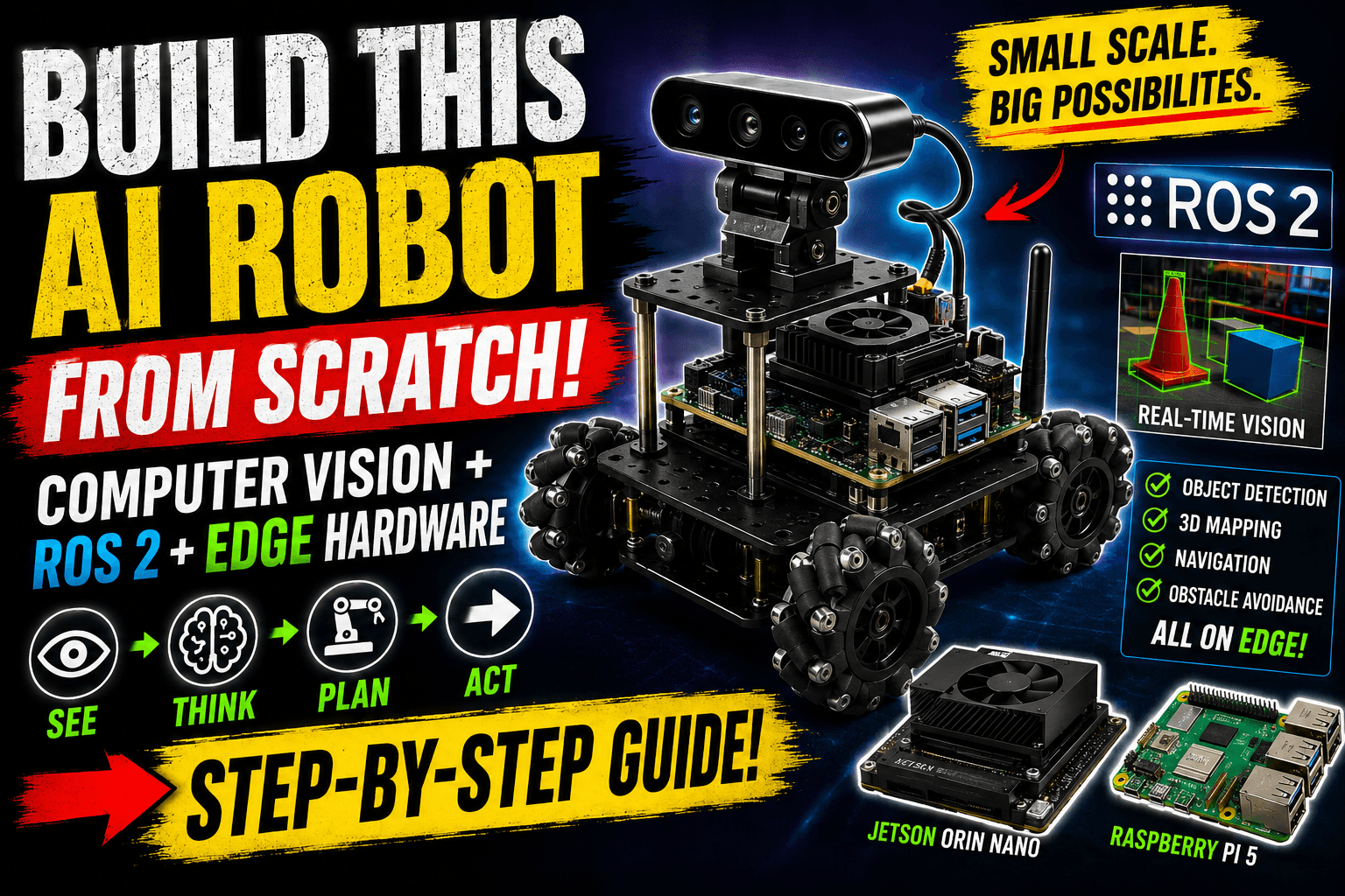
Building a computer-vision-capable robot used to require massive financial backing or mounting a heavy, battery-draining laptop onto a makeshift chassis.
The hardware landscape has changed completely. Thanks to the processing power of single-board computers like the Raspberry Pi 5 and low-power hardware accelerators, you can build a highly responsive, real-time spatial awareness rig for under ₹20,000 ($250).
When building a modern small-scale vision robot, the goal is to create a predictable distributed system using ROS 2 (Robot Operating System). The software framework ensures your camera node can capture video frames, pass them seamlessly to an AI model, and convert spatial coordinates into motor commands without locking up your system.
1. The Low-Cost Edge Hardware Stack
To prevent your robot from thermal throttling or running out of memory mid-execution, select your components with a strict focus on data throughput.
| Component | Target Selection | Role in the Rig | Approx. Price |
|---|---|---|---|
| The Brain | Raspberry Pi 5 (8GB) | Runs the ROS 2 workspace, handles overall network architecture, and coordinates node execution. | ~₹7,500 |
| The Accelerator | Hailo-8L M.2 AI Acceleration Module | Offloads object detection (YOLOv11) and spatial segmentation from the CPU. | ~₹6,000 |
| The Vision Sensor | Raspberry Pi Camera Module 3 or a basic Logitech C920 | Capture stable, native raw video feeds directly via MIPI CSI or USB bus. | ~₹2,500 |
| The Actuator Co-Processor | ESP32 Development Board | Runs micro-ROS natively to handle strict real-time motor encoder tracking and PWM signaling. | ~₹500 |
Critical Setup Warning: Do not install standard Raspberry Pi OS if you want an headache-free ROS 2 experience. Flash Ubuntu 24.04 LTS Server (64-bit). The latest long-term distribution of ROS 2 (ROS 2 Jazzy Jalisco) targets Ubuntu 24.04 natively, saving you from spending hours compiling dependencies from raw source files.
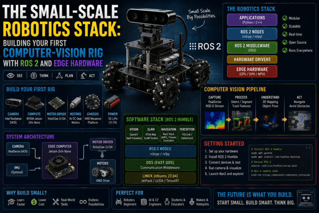
2. Architecting the Core ROS 2 Vision Pipeline
In a well-designed computer vision robot, your image pipeline is modular. Instead of writing one giant script that does everything, you break the functionality into isolated blocks called Nodes that communicate using a standard Publisher/Subscriber topology.
+---------------------------------------------------------------------------------+
|                                Raspberry Pi 5                                   |
|                                                                                 |
|  [ Camera Node ] --( Topic: /image_raw )--> [ Vision Inference Node (YOLO) ]    |
|         │                                                 │                     |
|         │ (Compressed Feed)                               │ (Topic: /detections)|
|         ▼                                                 ▼                     |
|  [ Foxglove Studio Studio (Remote PC) ]        [ Navigation / Motor Node ]      |
+---------------------------------------------------------------------------------+
                                                            │
                                                            ▼ (Serial Bus)
                                                   +------------------+
                                                   |  ESP32 Micro-ROS | -> Motors
                                                   +------------------+
Minimizing Latency (DDS Configuration)
The raw image stream coming out of an HD camera can easily swamp your internal memory bus if handled incorrectly. ROS 2 relies on Data Distribution Service (DDS) middleware to route information between nodes. To prevent your system from lagging seconds behind real-time events, use these settings:
- Use Shared Memory Transport: Ensure your nodes pass image references via pointers in system memory rather than serializing the entire image into a text string.
- Tweak the Quality of Service (QoS) Profiles: Set your camera publishing topic configuration to BEST_EFFORT, a history depth of 1. Your robot should drop a single frame occasionally rather than build a massive backlog queue of old frames while trying to maintain perfect transmission guarantees.
3. Step-by-Step Implementation
Building your environment requires strict build management. colcon.
Initialize the ROS 2 Workspace
5 mins
1 . Initialize the ROS 2 Workspace:5 mins.
Log in to your Raspberry Pi via SSH and establish your physical workspace directory layout.
Bash
mkdir -p ~/ros2_vision_ws/src
cd ~/ros2_vision_ws
colcon build
source install/setup.bash
Clone and Configure the Camera Wrapper
10 mins
2. Clone and Configure the Camera Wrapper:10 mins.
Rather than writing custom camera code, implement the optimized standard camera driver. Clone v4l2_camera into your /src directory. Configure the node parameters inside your initialization launch files to request YUYV pixel formats directly from the hardware.
Inject the Edge AI Model
20 mins
3. Inject the Edge AI Model:20 mins.
Deploy a specialized node leveraging the Hailo-8L runtime or run a lightweight model natively using OpenCV. This node subscribes to the /image_raw topic, performs detection bounding boxes, and outputs structured spatial coordinates onto a lightweight custom topic named /detections.
Bridge to the Actuators via Micro-ROS
15 mins
4 . Bridge to the Actuators via Micro-ROS:15 mins.
Flash your ESP32 with a micro-ROS sketch configured to listen to motor targets. The main Raspberry Pi calculates how far an object has drifted from the center of the camera screen and publishes direct directional velocity instructions geometry_msgs/msg/Twistdown to the motor controllers over a USB-serial line.
4. Visualizing Your Robot’s World Privately
When debugging your system, avoid running heavy graphics interfaces directly on your Raspberry Pi. This can take away critical processor cores needed by your vision algorithms.
Instead, leverage Foxglove Studio or launch a remote instance RViz2 on your primary developer laptop. By connecting both devices to the same local Wi-Fi router and sharing a matching ROS_DOMAIN_ID, your laptop will automatically discover and monitor the robot’s camera views and AI predictions in real-time.
For a complete look at a functioning small-scale robotics build utilizing these exact principles, check out this video demonstration of a MicroROS-Pi5 Robot Build. It illustrates how the combination of a Raspberry Pi 5, an ESP32 co-processor, and local vision processing looks when integrated onto a single low-cost physical chassis.